Technical Parameters |
Physical interface: 1-way, shielded super class V RJ45 seat, automatic turnover (Atuo MDI/MDIX) |
Connecting cable: Category 5 unshielded twisted pair |
Electrical interface: It supports and is compatible with 1000M, full duplex or half duplex Ethernet standards of international IEEE802.3 and ieee802.3u, and supports TCP and IP protocols |
Specific indicators of optical interface |
Optical fiber interface: SC/PC optional |
Light wavelength: Emission: 1270nm; Receiving: 1290nm (Optional) |
Communication distance: 0~5KM |
Fiber type: single mode single fiber (Optional) |
Size: 76(L) x 70(W) x 28(H)mm (Optional) |
Working temperature: -40~+85°C, 20~90RH%+ |
Working voltage: 5VDC |
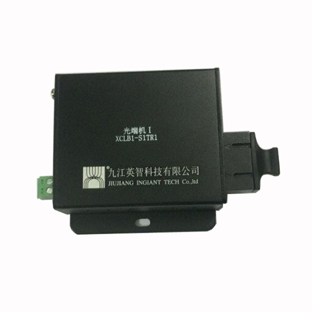
Appearance diagram and signal definition description:
Indicator light description |
PWR: Power indicator light is on when the power is connected normally |
+: DC power supply “+” |
– : DC power supply “-” |
FIB Optical fiber interface |
100/1000M: Ethernet interface |
There are two lights on the Ethernet RJ45 port: |
Yellow light: Ethernet link indicator light, on means the link is normal, flashing with data |
Green light: Optical fiber link indicator/activity light, on means the link is normal, flashing is data transmission |
Application description
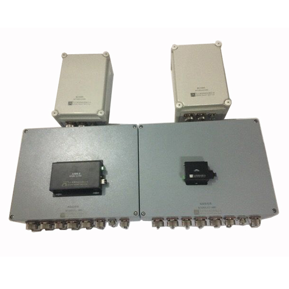
Generally, a star-shaped network is adopted, and the data signals such as TTL, analog voltage, Ethernet, telephone, RS-485 and other data generated by the front-end radar are transmitted to the field command center through the radar remote display extension and the field optical cable installed in the supporting cabin of the radar vehicle. The remote control display terminal of the radar, so that the front-end position can be operated synchronously through the operation seats of the command center.